
| Approach/Implementation | White Box | Black Box | ||
|---|---|---|---|---|
| Structural | Control-flow Data-flow |
|||
| Fault-based | Mutation | |||
| Error-based | Functional Random |
Control-flow Techniques
- Generate test cases taking into account the program control structure.
-
Based on the concept of coverage.
- Statement coverage
- Branch coverage
- Condition coverage
- Desision/condition coverage
- Multiple condition coverage
Example
IF (A OR B) THEN
    print C
Statement Coverage
Require each statement in the program been executed.
- (A OR B) = TRUE
e.g.
- T1: A=TRUE, B=FALSE
Branch Coverage
Require each breanch of each control structure been executed.
- (A OR B) = TRUE
- (A OR B) = FALSE
e.g.
- T1: A=TRUE, B=FALSE
- T2: A=FALSE, B=FALSE
Conditiona Coverage
Require each boolean sub-expression evaluated both to true and false.
- A = TRUE
- A = FALSE
- B = TRUE
- B = FALSE
e.g.
- T1: A=TRUE, B=FALSE
- T2: A=FALSE, B=TRUE
Decision/Condition Coverage
Requires that both decision and condition coverage been satisfied.
- A = TRUE
- A = FALSE
- B = TRUE
- B = FALSE
- (A OR B) = TRUE
- (A OR B) = FAKSE
e.g.
- T1: A=TRUE, B=FALSE
- T2: A=FALSE, B=TRUE
- T3: A=FALSE, B=FALSE
Multiple Condition Coverage
Require all the combinations of boolean sub-expressions should be evaluated
- A=TRUE, B=FALSE
- A=FALSE, B=TRUE
- A=FALSE, B=FALSE
- A=TRUE,B=TRUE
Basic Path Testing
Analyze the sequences of statements from the program input to output - paths of a program and drwa the control flow graph.
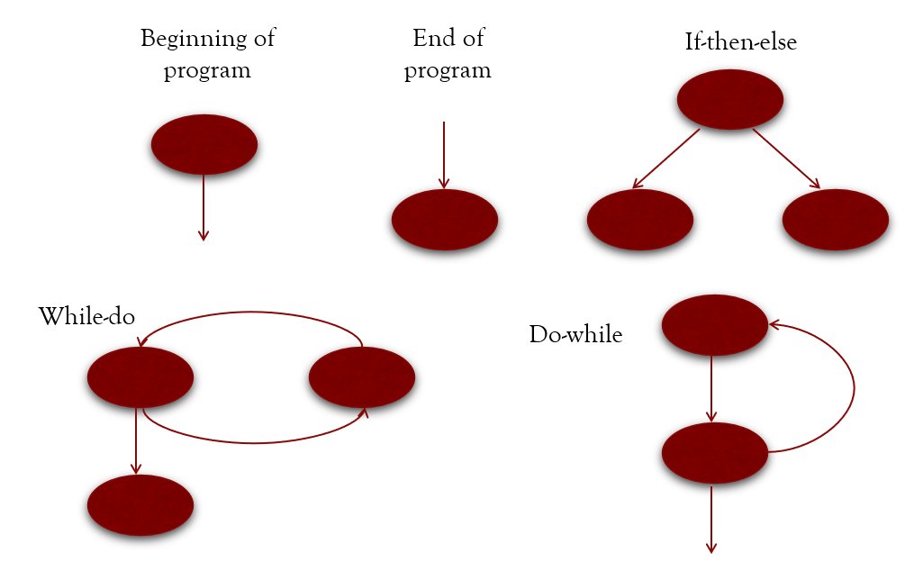
Flowchart
- Nodes: represent zero, one or more statements.
- Edges: link two nodes
- Regions: areas delimited by edges and nodes
- Predicate nodes: bifurcation node
Cyclomatic Complexity
-
C(G) represents complexity
- C(G) = Number of regions
- C(G) = Edges - Nodes + 2
- C(G) = Number of predicate nodes + 1
Determine Basic Set of Independent Paths - Equivalent to Decision/Consition Coverage
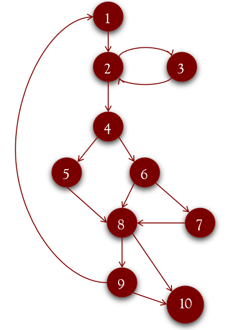
- 1 - 2 - 4 - 5 - 8 - 10
- 1 - 2 - 3 - 2 - 4 - 5 - 8 - 10
- 1 - 2 - 4 - 6 - 8 - 10
- 1 - 2 - 4 - 6 - 7 - 8 - 10
- 1 - 2 - 4 - 5 - 8 - 9 - 10
- 1 - 2 - 4 - 5 - 8 - 9 - 2 - 4 - 5 - 8 - 10
Modern Practice
- Check coverage using modern IDE
Functional Techniques
- Program is viewed as a black box
- They try to run test cases related to possible program faults
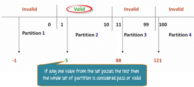
Equivalence Partitioning
- Divides the program input domain into data classes used to derive test cases.
- An equivalence class represents a set of valid or invalid states for program input conditions.
- Each input condition is examined and divided into two or more groups, identifying two types of classes
- An input condition typically refers to the set of values a given input can take
-
Two types of equivalence classes are defined:
- Valid equivalence classes: Represent valid program inputs.
- Invalid equivalence classes: Represent incorrect input values.
Value Range
- One valid and two invalid classes (above, below)
-
E.g.: counter range is from 1 to 999
- Valid class: 1 <= counter <= 999
- Invalid class: counter < 1
- Invalid class: a counter > 999
Number of Values
- One valid and two invalid classes
-
E.g.: a car can have from one to six owners in its lifetime
- Valid class: “from one to six owners”
- Invalid class: “there are no owners”
- Invalid class: “over six owners
Logical/Boolean Situation
- One of each type
- Sometimes a logical condition cannot be reduced to yes/no
-
E.g: the first character of the identifier should be a letter
- Valid class: “identifier starting with letter”
-
Invalid class: identifier not starting with letter
- starting with a number
- starting with a symbol
Set of input values
-
If there are reasons to believe that the program will treat each
group member differently, identify a valid class for each member,
and an invalid class
-
E.g. vehicle type is: bus, truck, car or motorbike
- 4 Valid classes: “bus”, “truck”, “car”, “motorbike”
- Invalid class: any other vehicle type, e.g., “cycle”, “mobile house”
-
E.g. vehicle type is: bus, truck, car or motorbike
Other
-
Generally, if there is any reason for believing that the program
does not treat the items of an equivalence class equally
E.g.: some phone prefixes are not admitted - Divide the equivalence class into smaller equivalence classes for each item type
Equivalence Partitioning’s Example
Banking application, where the user can perform some bank transactions. The information for accessing the transactions requires the following input:
Bank Code
Blank or three-digit number. The first digit of the three-digit number should be greater than 1.
-
Valid Equivalence Class
- Blank
- 3-digit number ranged from 200 <= Bank code <= 999
Branch Code
A four-digit number, the first of which is greater than 0.
-
Valid Equivalence Class
- 4-digit number, 1000 <= Branch code <=9999
-
Invalid Equivalence Class
- Non-numerical value
- Number of more than 4 digits
- Number of less than 4 digits
- 4-digit number, Branch code < 1000
Account Number
Five-digit number.
-
Valid Equivalence Class
- Any five-digit number
-
Invalid Equivalence Class
- Non-numerical value
- Number of more than five digits
- Number of less than five digits
Password
Five-position alphanumerical value.
-
Valid Equivalence Class
- Any five-position alphanumerical character string
-
Invalid Equivalence Class
- Non-alphanumerical character string
- String of less than five positions
- String of more than five positions
Order
Either blank or one of the following two strings: “Checkbook” or “Transactions”
-
Valid Equivalence Class
- “Checkbook”
- “Transactions”
-
Invalid Equivalence Class
- Any string that is not the empty or the same as the valid strings
Generate Test Cases
- Write a case to cover as many uncovered valid classes as possible until the test cases cover all the valid equivalence classes
- Write a case to cover just one uncovered invalid classes until the test cases cover all the invalid equivalence classes
Boundary Value Analysis
- Instead of selecting just any test case in the valid and invalid classes, you test the edges between equivalence partitions
- Instead of focusing just on the input domain, it designs the test cases also taking into account the output domain
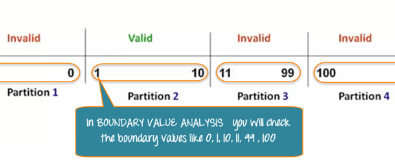
Value Range
Design test cases for the two bounds of the range, and another two cases for situations just above and just below these bounds
Number of Values
Design two test cases for the minimum and maximum values, as well as another two test cases for values just above the maximum and just below the minimum
Order Set
Pay attention to the first and last elements of the set.
Output
Apply the above rules to output data as well
Blackbox Testing Technique
Decision Table Technique
- Decision table technique is widely used for black box testing.
- This is a systematic approach where various input combinations and their respective system behavior are captured in a tabular form.
- Decision table technique is appropriate for the functions that have a logical relationship between two and more than two inputs.
| Input 1 (Tow Possible Values) | Possible Value 1 | Possible Value 2 | Possible Value 1 | Possible Value 2 | Possible Value 1 | Possible Value 2 |
| Input 2 (Three Possible Values) | Possible Value 1 | Possible Value 1 | Possible Value 2 | Possible Value 2 | Possible Value 3 | Possible Value 3 |
| Expected Result | Expected Result 1 | Expected Result 2 | Expected Result 3 | Expected Result 4 | Expected Result 5 | Expected Result 6 |
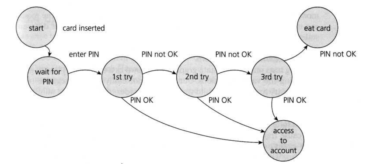
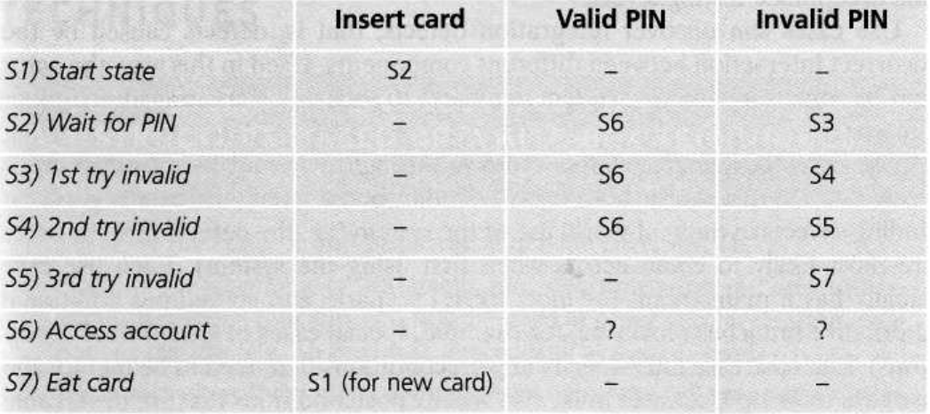
State Transition Technique
- State transition testing is used where some aspect of the system can be described in what is called a ‘finite state machine’.
- This method tests whether the function is following state transition specifications on entering different inputs.
- Any system where you get a different output for the same input, depending on what has happened before, is a finite state system.
- We usually use state diagram to represent such system.
- The transitions from one state to another are determined by the rules of the ‘machine’.
Transition Model
- the states that the software may occupy
- the transitions from one state to another
- the events that cause a transition
- the actions that result from a transition
PIN Example
Web Login Example
| State | Login | Validation | Next State |
|---|---|---|---|
| S1 | First Attempt | Invalid | S2 |
| S2 | Second Attempt | Invalid | S3 |
| S3 | Third Attempt | Valid | S4 |
| S4 | Redirect to Home page | ||
| S5 | Redirect to Error Page |
| State | Login | Validation | Next State |
|---|---|---|---|
| S1 | First Attempt | Invalid | S2 |
| S2 | Second Attempt | Invalid | S3 |
| S3 | Third Attempt | Invalid | S5 |
| S4 | Redirect to Home page | ||
| S5 | Redirect to Error Page |
Test Case Specification
Test goal
High level description of the purpose of the test case.
Inputs
Actual inputs given to the program.
Expected outputs
Description of the program output according to the specification.
Observed outputs
Description of the program output when it is run
Failure Identification
Failures are identified by comparing expected outputs against observed outputs.